JOIN GEOSHARE
Potomac River Tunnel Project, Washington DC, USA
OVERVIEW
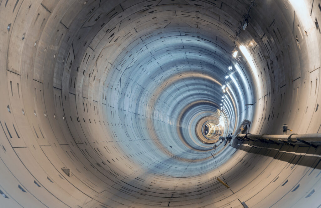
The Potomac River Tunnel is a major component of DC Water’s Clean Rivers Project, designed to capture and store combined sewer overflows and stormwater during heavy rain events before transferring them to the Blue Plains Advanced Wastewater Treatment Plant.
The 100-foot-deep (30m) tunnel system will significantly expand sewer capacity and is expected to reduce untreated discharges to the Potomac River by approximately 93%.
Various Geosense sensor systems will enable monitoring of the 5.5-mile (8.9 km) long main tunnel and ancillary shafts throughout the construction process.
Project Summary
- Name
- Potomac River Tunnel Project, Washington DC, USA
- Location
- Washington DC, United States of America
- Date
- 2025

The Challenge
Construction involves two tunnel boring machines (TBMs) operating in contrasting geological conditions, with one mining south through mostly soft ground (clay, alluvium) and one from West Potomac Park heading north to bore through hard rock.
The 18-foot (5.5m) diameter main tunnel passes close to several of Washington D.C.’s iconic monuments, demanding precise control of vibration and settlement.
Ancillary structures comprise 9 shafts, adits connecting to the main tunnel, and near-surface structures which link the new infrastructure to the existing sewage system.
Monitoring
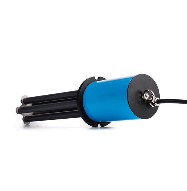
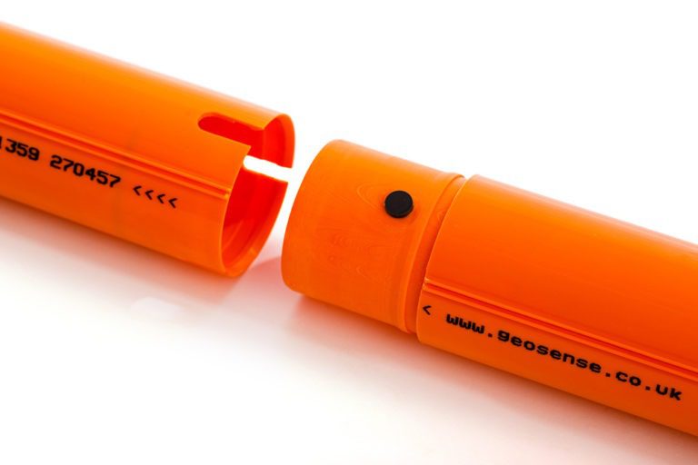
Vibrating Wire Piezometers were deployed to monitor pore water pressure variations during tunnelling, providing critical data on groundwater behaviour. The VWP-3000 Series of Vibrating Wire piezometers was chosen, using the well-proven method of converting fluid pressures on a sensitive diaphragm into a frequency signal.
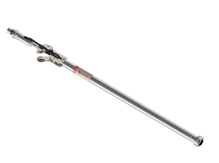
Geosense Multi-Point Borehole Rod Extensometers (MPBX) were installed at strategic locations to monitor the depth, magnitude, and rate of ground movement around the tunnel lining. Anchors at set depths were linked to a surface reference head. As the soil, rock, or concrete deforms, the system precisely indicates where and how the ground is shifting.
More than 200 In-Place Inclinometers (IPI) were installed to monitor lateral ground movement, ensuring compliance with design limits throughout TBM operation. The Biaxial Digital MEMS version was specified over the uniaxial version due to its greater ability to detect movement in multiple directions.
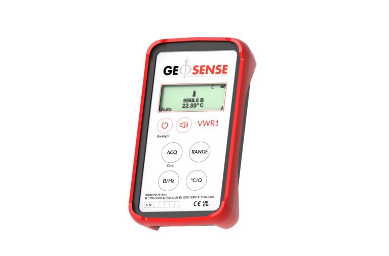
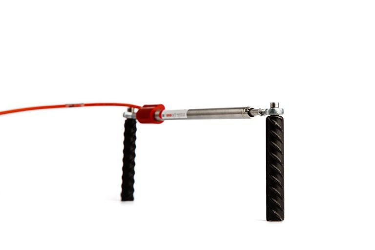
Vibrating wire crack meters were also utilised in the project, grouted to joints in concrete in order to measure movement and read by the VWR1, a compact manual readout unit.