JOIN GEOSHARE
Crossrail C310: Thames Tunnel
Following the successful Channel Tunnel Rail Link contract, joint venture partners HOCHTIEF Solutions AG and Murphy & Sons Limited were awarded the C310 project. In association with engineers from the Cambridge Centre for Smart Infrastructure and Construction (CSIC), at the University of Cambridge, it was agreed to instrument four rings at several locations within the eastbound tunnel of Plumstead-North Woolwich Tunnel in order to measure ring deformations prior to, during and after construction.
Geosense sensors were used in conjunction with Fibre Optic sensors provided by Cambridge University. Geosense sensors were to act as a benchmark for the Fibre Optic sensors.
The segments to be instrumented were modified to facilitate installation and accessibility to the monitoring instrumentation. The aim was to monitor the strains encountered in several segments during the cycle of the segment from manufacture to installation. They were manufactured just outside Dublin, transported to Liverpool and then down to the C310 site and finally to the TBM for installation.
Project Summary
- Name
- Crossrail C310: Thames Tunnel
- Location
- UK
- Date
- June 2014
- Client
- Crossrail Ltd
- Contractor
- Hochtief Solutions AG and J.Murphy & Sons
- Instrumentation Specialist
- Cambridge Centre for Smart Infrastructure and Construction (CSIC)


Monitoring
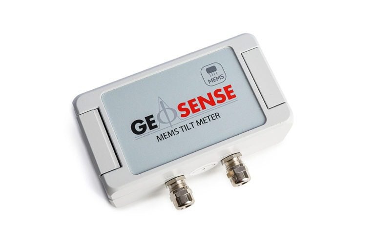
Biaxial Tilt Loggers were installed in a steel box measuring 268x181x133mm which was cast into the concrete rings of the tunnel. These would effectively measure the convergence of the tunnel.
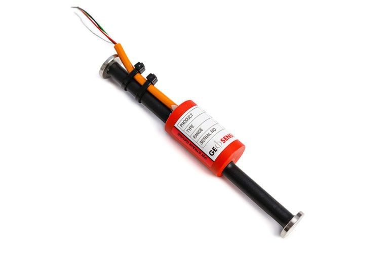
In addition, Embedded Strain Gauges were installed in the concrete segments themselves to monitor any minute movements within the tunnel and provide baseline data. These were then connected to the 10 Channel loggers which were also installed in the steel boxes.
Due to the space constraints within the steel box, Geosense had to manufacture special mounting plates and cable gland plates (which also needed to meet the EMC regulations to reduce the chance of electrical interference), which not only fitted inside the box but also allowed for the tilt sensors to be adjustably mounted in the right orientation to be able to measure within their +/- 15° calibrated range.
Further into the project, extra-long USB cables will need to be installed connecting the 10 Channel loggers and tilt loggers to a central terminal box where the data can be downloaded.
Due to the limitations of USB signal degradation, cables with signal boosters are to be used.